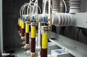
SERIES REACTOR PROVIDED WITH HT CAPACITORBANKS :
HT Capacitors are usually provided with Series Reactors. There are generally 2 types of Series Reactors
a) 6% Series Reactor. This is provided on the line end of the CapacitorBank as follows: –
b) 0.2% Series Reactor:This is provided on the neutral end of the CapacitorBank as follows
TYPE OF CONNECTION OF HT CAPACITOR BANKS
HT Capacitors are mostly connected in single star / double star. For 3.3 KV and 6.6 KV CapacitorBank we generally give ThreePhase units like LT Capacitors. However the minimum rating of Capacitor for 3.3 KV / 6.6 KV 3 Phase is 75 KVArand above upto 200 KVAr.
For 11 KV 1 Phase HT Capacitors are connected in either star or double star like
INTERNAL CONNECTION OF HT CAPACITOR UNIT AND STRESS FACTOR
The construction of HT Capacitors is similar to that of LT APP TypeCapacitors. The basic element consists of 2 layers of conducting medium in the form of Alluminium foil and 3 layers of (instead of One layer in LT Capacitors) PP film. This is since the application of HT Capacitors is critical and the voltage across the element is higher as compared to LT Capacitor.
Voltage Stress is an important factor for HT Capacitors. The rates of Capacitors depend solely on the stress level adopted by the Manufacturer. Hence there will always be significant variations between prices of: • Different Types of application. I.e.: SEBS and industries especially steel industries • Between Manufacturer to Manufacturer
WHAT IS STRESS?
The voltage that is applied across per micron thickness of the dielectric is called as stress in terms of volts per micron. This can be demonstrated by the following figure: –
The thickness of dielectric 10.1 x 3 = 30.3 microns.
Total Voltage across all the 3 layers = 1825 V
Hence Stress = 1825 V 30.3 microns
= 60.23 Volts per microns
Capacitors of SEBS are generally designed at 70 Volts per micron and for industrial application the stress adopted is around 58V / 60V per micron.
TESTS ON HT CAPACITORS
There are 2 types of tests carried out on HT Capacitors
a) Routine Tests- These tests are carried out on each and every Capacitor at the factory itself
b) Type Test – These are carried out once in every 3 or 5 Years on a GovernmentApprovedIndependentLab like CPRI & ERDA
c) Endurance Test – this is a long duration test that is performed to check the performace of Capacitor as per the demands at site. Since it is a high cost and a long duration test it is recommended to be carried out once in 10 years.
Usually Govt. Tenders demand copy of TypeTestCertificates, which are less, than 3 to 5 Years old.