HARMONICS MITIGATION TECHNIQUES
We all know that in a pure sinusoidal waveform having inductive load the current leads the voltage by 90 degrees. The current drawn by the load is proportional to the voltage and impendence.But this is true only in case of pure linear loads. Resistive loads, constant speed induction and synchronous motors are pure linear loads.
In contrast, there are some loads that can cause the current to vary disproportionately to the voltage at each cycle. These are due to non-linear loads and thus the cause a non-sinusoidal waveform or distorted waveform. Actually, within one cycle of the wave form multiple waveform are embedded thus creating multiple frequencies within the normal 50 cycle wave. The current distortions of the load tend to disturb the voltage waveform and consequently distort the voltage. Some examples of non-linear loads are battery chargers, electronic ballasts, variable frequency drives and any other machines with needs convertors.
EFFECTS OF HARMONICS ON THE ELECTRICAL SYSTEM :
As you have seen current distortions cause variations in impedance and eventually distorts the voltage. These conditions can create overloads on machine and electronic equipment. Also, the overloads can over stress the cables which carries voltage from source to the loads. The transformers are also overloaded and if these are designed for optimum capacity these transformers could fail prematurely. Protection and measurement components are designed to work of fundamental frequency and any distortionsin the waveform can cause spurious operations. All these host of ill-effects can lead to frequent outage and production and revenue losses. In a nutshell the ill effects of harmonic to the electrical system is as under :
TABLE ILL EFFECTS OF HARMONICS
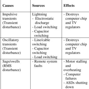
Hence the need is to mitigate the harmonics as it is unavoidable is present times when non-linear loads are essential for modern day needs and the latest trends adopted by the manufacturing and infrastructure units.
MITIGATION OF HARMONICS :
It’s better to light the candle than curse the darkness – as we have to accept the electrical systems have to bear the brunt of the harmonics overloads it is imperative to counter this menace with effectively with appropriate harmonic filters. These filters are cumbersome and involves cost and maintenance. Hence implementing the same without proper assessment is not recommended. To understand the need to provide harmonic filter a simple flow chart is given below :
FLOW CHART
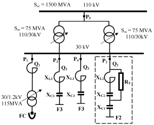
PLANNING OF HARMONIC FILTER BANKS
PICTURE A